|
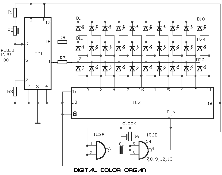
This digital color organ tracks both the amplitude
and frequency of the sound input. In operation the phone output of
a transistor radio can be connected directly to the input of the
LM3915. Sensitivity is adjusted through R2 and may need to adjusted
if the volume is changed. The display unit consists of 10 tricolor
clusters of LEDs with red representing low, yellow midrange, and
green high ranges. 2 gates of a 4011 are used to make a clock,
which can adjusted through R6, and fed into the clock input on
IC2 (4017). When there is no sound the display will be blank.
Once a signal is present the display will come to life with
bursts of light and bars as the signal is tracked. Resistors
R4 and R5 can initially start with a 1Kohm pot to achieve the
best balance and replaced with fixed resistors once this is
determined. The display can be expanded by cascading additional
4017's and LED clusters.
|
| R1=
1.8Kohm |
R6=
100Kohm trimmer |
IC1=
LM3915 |
| R2=
100Kohm trimmer |
C1=
0.1uF 100V |
IC2=
4017 |
| R3=
1Kohm |
D1....10= RED LED |
IC3=
4011 |
| R4=
100 ohm.....1Kohm |
D11....20= YELLOW LED |
|
| R5=
100 ohm.....1Kohm |
D21....30= GREEN LED |
| |
|
